Programming Mecanum Wheels
Published: 18 November 2022
By: Orville Daley
The Physics of Mecanum
Mecanum wheels are a unique kind of wheel that, in contrast to conventional wheels, allow for mobility and holonomic strafing. They are made up of a number of rubber rollers that have been turned 45 degrees to the left or right.
In a typical mecanum drivetrain, sideways motion is produced by turning the wheels on one diagonal in the opposite direction from the wheels on the other diagonal. These wheel motions may be combined to move the vehicle in any direction and make it rotate in any direction.
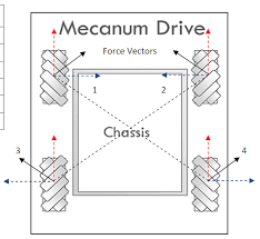
The four mecanum wheels in a typical mecanum drive system are arranged in a "X" pattern. This indicates that when viewed from above, the rollers are inclined toward the center. The force vectors generated by the offset rollers can be summed and equations for movements in all directions can be derived.

Vectors 1, 2, 3, and 4 in the figure above represent the force vectors produced by the mecanum wheels when the chassis is told to move toward the top of the picture. Every motor is moving ahead. Their X and Y components are shown by the blue and red lines, respectively.
Note DO NOT HARDCODE THE WHEEL MOVEMENTS, THESE CAN BE PROGRAMMATICALLY COMPUTED
Note It is important to note that because of friction, perfect movement isn’t possible in every direction.
Deriving Mecanum Control Equations
Direction
Because the motors are facing away from each other, one side of your robot's motor should be reversed. If your mecanum wheels are connected directly to the motors then reverse the left side motors. If your mecanum wheels are connected to with a gear ratio then reverse the right side motors.
 SET leftBackMotor DIRECTION TO REVERSE
 SET leftFrontMotor DIRECTION TO REVERSE
Linear Motion
Joysticks can be used to input x and y coordinates. The forward motion is controlled by the y-axis and the sideways motion (strafe) is controlled by the x-axis.
Reminder The y-axis is inverted, so the forward motion is negative when the joystick is pushed forward.
 SET forward TO -gamepad1.left_stick_y
 SET strafe TO gamepad1.left_stick_x
Deriving Linear Motion Equations
For the robot to move forward, we would need all wheels to have a positive power. Therefore, in the equation, all motor equation have forward as positive.
 SET leftFrontMotorPower TO forward
 SET rightFrontMotorPower TO forward
 SET leftBackMotorPower TO forward
 SET rightBackMotorPower TO forward
To incorporate strafing, consider moving right, ie: a positive strafe value. We would require left wheels to move in opposite direction away from each other (with the front left wheel going forward). We would also need the right going in opposite direction coming together (with the front right wheel going backward). This can be seen in the figure 1.
 SET leftFrontMotorPower TO forward + strafe
 SET rightFrontMotorPower TO forward - strafe
 SET leftBackMotorPower TO forward - strafe
 SET rightBackMotorPower TO forward + strafe
Rotational Motion
The turning motion is controlled by the x-axis of the right joystick. Moving the joystick to the right will cause the robot to turn clockwise.
SET turn TO gamepad1.right_stick_x
Deriving Rotational Motion Equations
To turn clockwise, we would need the right wheels to move backwards whilst the left wheels are moving forward.
 SET leftFrontMotorPower TO turn
 SET rightFrontMotorPower TO -turn
 SET leftBackMotorPower TO turn
 SET rightBackMotorPower TO -turn
Combining Linear and Rotational Motion
To combine linear and rotational motion, we would need to add the rotational motion to the linear motion equations.
 SET leftFrontMotorPower TO forward + strafe + turn
 SET rightFrontMotorPower TO forward - strafe - turn
 SET leftBackMotorPower TO forward - strafe + turn
 SET rightBackMotorPower TO forward + strafe - turn
Normalizing Motor Powers
The motor powers are normalized to ensure that the robot moves uniformly. If a motor has a power greater than 1 then it clipped to 1. This would lead to the robot moving weirdly.
 SET maxPower TO MAX( 1, ABS(forward) + ABS(strafe) + ABS(turn) )
 SET leftFrontMotorPower TO leftFrontMotorPower / maxPower
 SET rightFrontMotorPower TO rightFrontMotorPower / maxPower
 SET leftBackMotorPower TO leftBackMotorPower / maxPower
 SET rightBackMotorPower TO rightBackMotorPower / maxPower
The Full Pseudocode
START
    # Remember one side of the robot's wheel should be reversed: the left side.

    SET forward TO -gamepad.left_stick_y # The y axis of the joystick is flipped with regards to the cartesian plane.
    SET strafe TO gamepad.left_stick_x
    SET turn TO gamepad.right_stick_x

    SET leftFrontMotorPower TO forward + strafe + turn
    SET rightFrontMotorPower TO forward - strafe - turn
    SET leftBackMotorPower TO forward - strafe + turn
    SET rightBackMotorPower TO forward + strafe - turn

    SET maxPower TO MAX( 1, ABS(forward) + ABS(strafe) + ABS(turn) )
    SET leftFrontMotorPower TO leftFrontMotorPower / maxPower
    SET rightFrontMotorPower TO rightFrontMotorPower / maxPower
    SET leftBackMotorPower TO leftBackMotorPower / maxPower
    SET rightBackMotorPower TO rightBackMotorPower / maxPower

    SET leftFrontMotor POWER TO leftFrontMotorPower
    SET rightFrontMotor POWER TO rightFrontMotorPower
    SET leftBackMotor POWER TO leftBackMotorPower
    SET rightBackMotor POWER TO rightBackMotorPower

STOP.
The Full Blocks Code

Citations and Additional Resources
https://www.youtube.com/watch?v=gnSW2QpkGXQ
https://www.youtube.com/watch?v=Xrc0l4TDnyw
https://www.youtube.com/watch?v=Ne09Y72zW_Y
https://seamonsters-2605.github.io/archive/mecanum/
https://ftcforum.usfirst.org/forum/ftc-technology/android-studio/6361-mecanum-wheels-drive-code-example
https://www.tutorialspoint.com/java/number_atan2.htm
http://thinktank.wpi.edu/resources/346/ControllingMecanumDrive.pdf